- 您现在的位置:买卖IC网 > Sheet目录3818 > PIC18F4620-I/ML (Microchip Technology)IC MCU FLASH 32KX16 44QFN
PIC17C4X
DS30412C-page 100
1996 Microchip Technology Inc.
14.1
Conguration Bits
The PIC17CXX has up to seven conguration locations
(Table 14-1). These locations can be programmed
(read as '0') or left unprogrammed (read as '1') to select
various device congurations. Any write to a congura-
tion location, regardless of the data, will program that
conguration bit. A TABLWT instruction is required to
write to program memory locations. The conguration
bits can be read by using the TABLRD instructions.
Reading any conguration location between FE00h
and FE07h will read the low byte of the conguration
word (Figure 14-1) into the TABLATL register. The TAB-
LATH register will be FFh. Reading a conguration
location between FE08h and FE0Fh will read the high
byte of the conguration word into the TABLATL regis-
ter. The TABLATH register will be FFh.
Addresses FE00h thorough FE0Fh are only in the pro-
gram memory space for microcontroller and code pro-
tected microcontroller modes. A device programmer
will be able to read the conguration word in any pro-
cessor mode. See programming specications for more
detail.
TABLE 14-1:
CONFIGURATION
LOCATIONS
Bit
Address
FOSC0
FE00h
FOSC1
FE01h
WDTPS0
FE02h
WDTPS1
FE03h
PM0
FE04h
PM1
FE06h
PM2 (1)
FE0Fh (1)
Note 1: This location does not exist on the
PIC17C42.
Note:
When programming the desired congura-
tion locations, they must be programmed in
ascending order. Starting with address
FE00h.
14.2
Oscillator Congurations
14.2.1
OSCILLATOR TYPES
The PIC17CXX can be operated in four different oscil-
lator modes. The user can program two conguration
bits (FOSC1:FOSC0) to select one of these four
modes:
LF:
Low Power Crystal
XT:
Crystal/Resonator
EC:
External Clock Input
RC:
Resistor/Capacitor
14.2.2
CRYSTAL OSCILLATOR / CERAMIC
RESONATORS
In XT or LF modes, a crystal or ceramic resonator is
connected to the OSC1/CLKIN and OSC2/CLKOUT
pins
to
establish
oscillation
The
PIC17CXX Oscillator design requires the use of a par-
allel cut crystal. Use of a series cut crystal may give a
frequency out of the crystal manufacturers specica-
tions.
For frequencies above 20 MHz, it is common for the
crystal to be an overtone mode crystal. Use of overtone
mode crystals require a tank circuit to attenuate the
gain at the fundamental frequency. Figure 14-3 shows
an example of this.
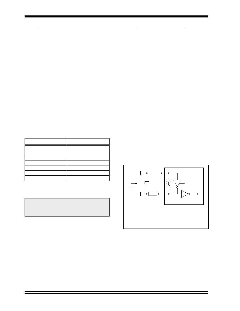
FIGURE 14-2: CRYSTAL OR CERAMIC
RESONATOR OPERATION
(XT OR LF OSC
CONFIGURATION)
See Table 14-2 and Table 14-3 for recommended
values of C1 and C2.
Note 1:
A series resistor may be required for AT strip
cut crystals.
C1
C2
XTAL
OSC2
Note1
OSC1
RF
SLEEP
PIC17CXX
To internal
logic
发布紧急采购,3分钟左右您将得到回复。
相关PDF资料
PIC24HJ256GP210-I/PT
IC PIC MCU FLASH 128KX16 100TQFP
PIC24HJ128GP310A-I/PF
IC PIC MCU FLASH 128KB 100-TQFP
DSPIC33FJ128GP310-I/PF
IC DSPIC MCU/DSP 128K 100TQFP
PIC16C66-20I/SO
IC MCU OTP 8KX14 PWM 28SOIC
DSPIC33FJ128MC510-I/PT
IC DSPIC MCU/DSP 128K 100TQFP
PIC16C66-20I/SP
IC MCU OTP 8KX14 PWM 28DIP
PIC18LF2620-I/SP
IC MCU FLASH 32KX16 28SDIP
PIC16F877-04I/P
IC MCU FLASH 8KX14 EE 40DIP
相关代理商/技术参数
PIC18F4620-I/P
功能描述:8位微控制器 -MCU 64KB 3968 RAM 36 I/O RoHS:否 制造商:Silicon Labs 核心:8051 处理器系列:C8051F39x 数据总线宽度:8 bit 最大时钟频率:50 MHz 程序存储器大小:16 KB 数据 RAM 大小:1 KB 片上 ADC:Yes 工作电源电压:1.8 V to 3.6 V 工作温度范围:- 40 C to + 105 C 封装 / 箱体:QFN-20 安装风格:SMD/SMT
PIC18F4620-I/P
制造商:Microchip Technology Inc 功能描述:IC 8BIT FLASH MCU 18F4620 DIP40
PIC18F4620-I/PT
功能描述:8位微控制器 -MCU 64KB 3968 RAM 36 I/O RoHS:否 制造商:Silicon Labs 核心:8051 处理器系列:C8051F39x 数据总线宽度:8 bit 最大时钟频率:50 MHz 程序存储器大小:16 KB 数据 RAM 大小:1 KB 片上 ADC:Yes 工作电源电压:1.8 V to 3.6 V 工作温度范围:- 40 C to + 105 C 封装 / 箱体:QFN-20 安装风格:SMD/SMT
PIC18F4620-I/PT
制造商:Microchip Technology Inc 功能描述:IC 8BIT FLASH MCU 18F4620 TQFP44
PIC18F4620T-I/ML
功能描述:8位微控制器 -MCU 64KB 3968 RAM 36 I/O RoHS:否 制造商:Silicon Labs 核心:8051 处理器系列:C8051F39x 数据总线宽度:8 bit 最大时钟频率:50 MHz 程序存储器大小:16 KB 数据 RAM 大小:1 KB 片上 ADC:Yes 工作电源电压:1.8 V to 3.6 V 工作温度范围:- 40 C to + 105 C 封装 / 箱体:QFN-20 安装风格:SMD/SMT
PIC18F4620T-I/PT
功能描述:8位微控制器 -MCU 64KB 3968 RAM 36 I/O RoHS:否 制造商:Silicon Labs 核心:8051 处理器系列:C8051F39x 数据总线宽度:8 bit 最大时钟频率:50 MHz 程序存储器大小:16 KB 数据 RAM 大小:1 KB 片上 ADC:Yes 工作电源电压:1.8 V to 3.6 V 工作温度范围:- 40 C to + 105 C 封装 / 箱体:QFN-20 安装风格:SMD/SMT
PIC18F4680-E/ML
功能描述:8位微控制器 -MCU 64KB 3328 RAM w/ECAN RoHS:否 制造商:Silicon Labs 核心:8051 处理器系列:C8051F39x 数据总线宽度:8 bit 最大时钟频率:50 MHz 程序存储器大小:16 KB 数据 RAM 大小:1 KB 片上 ADC:Yes 工作电源电压:1.8 V to 3.6 V 工作温度范围:- 40 C to + 105 C 封装 / 箱体:QFN-20 安装风格:SMD/SMT
PIC18F4680-E/P
功能描述:8位微控制器 -MCU 64KB 3328 RAM w/ECAN RoHS:否 制造商:Silicon Labs 核心:8051 处理器系列:C8051F39x 数据总线宽度:8 bit 最大时钟频率:50 MHz 程序存储器大小:16 KB 数据 RAM 大小:1 KB 片上 ADC:Yes 工作电源电压:1.8 V to 3.6 V 工作温度范围:- 40 C to + 105 C 封装 / 箱体:QFN-20 安装风格:SMD/SMT